Pneumatic vibratory drives | Silo accessories
Piston vibrators linear type F
Our compressed air driven piston vibrators linear of the F series are suitable, for example, for compacting, loosening or screening at conveyor troughs, discharge troughs or for bunker emptying. Due to the linear vibration generated, the piston vibrators are suitable for many other applications that require a linear direction of vibration and compactness. These pneumatic vibrators are available in various performance classes and are also suitable for direct drive of small conveyor troughs or linear vibrators.
- Description
- Performance data
- Dimensions
- Data sheets
Pneumatic piston vibrators linear of the F series are used to support material flow, screening, compacting, sorting, loosening, conveying and cleaning by means of vibration.
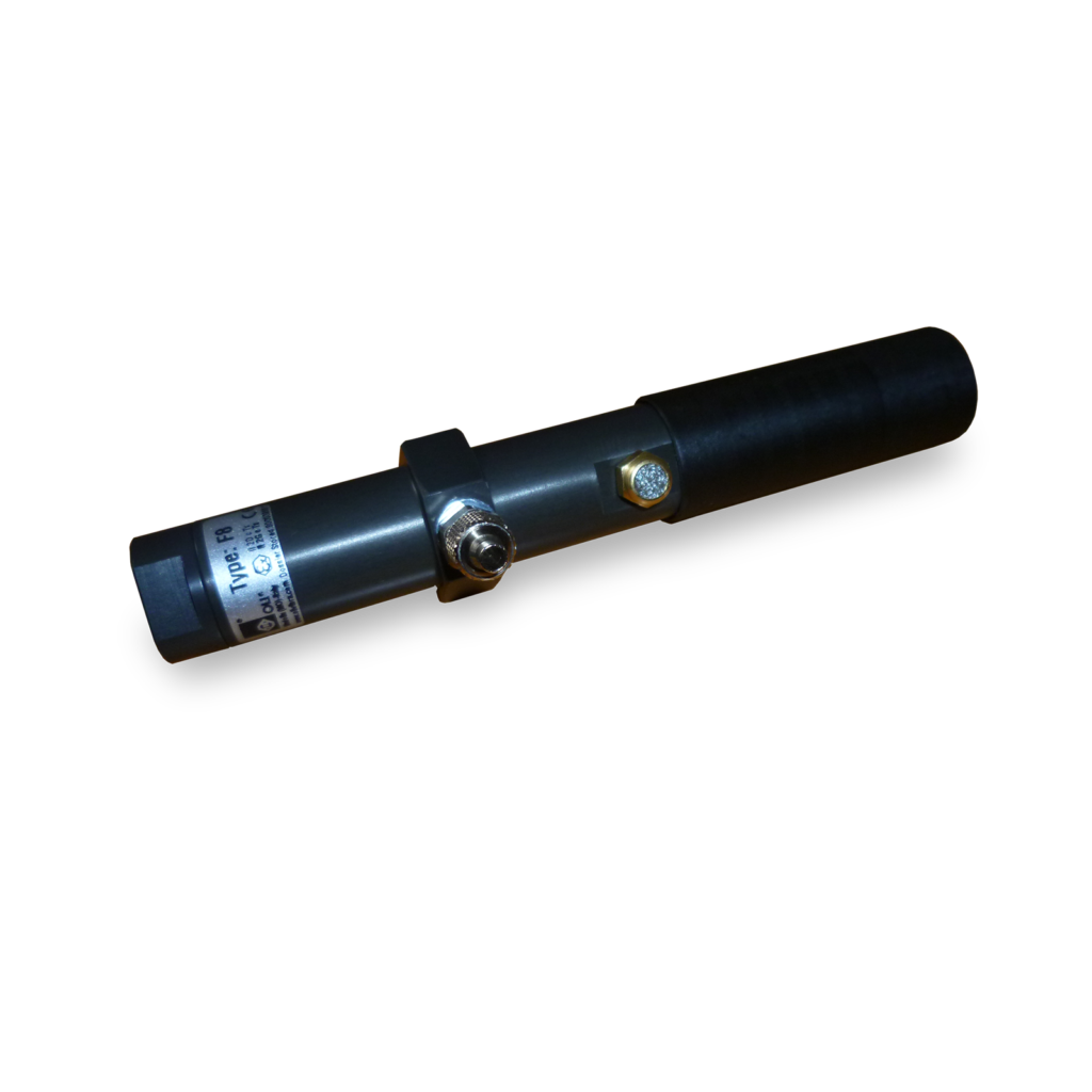
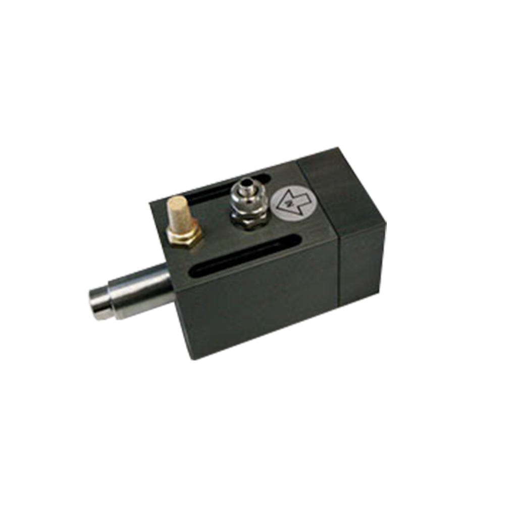
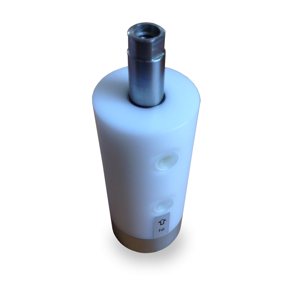
These piston vibrators are suitable for applications where special emphasis is placed on an exactly linear direction of the force. They are available in various structural designs: cylindrical, hexagonal (F8 only) and cuboid (F18Q only).
They have a piston emerging from the housing, on which there are fastening possibilities. This type of piston vibrator can therefore be used, for example, as a vibratory drive for small conveyor troughs or similar installations.
Alternatively, our piston vibrators type K can be used, which have a closed housing with a completely encapsulated and internal piston.
Technical features
- explosion-proof
- maintenance-free
- frequency and amplitude adjustable
- large vibration amplitudes
- optimal start-stop behavior
- start in any position
- minimal noise emissionlow air consumption
Field of application
These vibrators are suitable for the following applications:
- Vibratory drive for small discharge chutes or conveyor troughs
- knocking off adhesions on the walls of bunkers, hoppers, containers and silos
- Drive for small vibrating tables and chutes
- Discharge aid for bins
- Maintaining material flow and clearing product jams
Vibration
Vibration is generated by means of a self-reversing piston guided in a cylinder.
This piston is blown with compressed air, which causes it to move linearly in the cylinder guide towards the end position. The direction of movement is reversed in the end position by the self-reversing action and the piston moves in the direction of the other end position. In this position, the direction of movement is also reversed. The inertia of the mass of the piston causes a force effect. This force effect is transmitted to the structure as a vibration (due to the continuous reversal).
The piston vibrators generate a linear and sinusoidal vibration due to this active principle.
Pressure/temperature
The piston vibrators are operated with up to 6 bar of compressed air. The frequency of the vibration can be increased/decreased by throttling the air supply.
The standard operating temperature is -10°C to +150°C (for model F15P only 0°C to +100°C).
Protection/Safety
Our piston vibrators type F are equipped with the CE mark.
| Schwingfrequenz 1/min | Arbeitsmoment kg*cm | Kraft N | Luftverbrauch NL/min | |||||||
|---|---|---|---|---|---|---|---|---|---|---|
| 2 bar | 4 bar | 6 bar | 6 bar | 2 bar | 4 bar | 6 bar | 2 bar | 4 bar | 6 bar | |
| F8 | 2.020 | 2.950 | 3.600 | 0,04 | 10 | 23 | 34 | 7 | 19 | 28 |
| F15 | 2.280 | 2.520 | 2.820 | 0,22 | 48 | 78 | 98 | 20 | 38 | 67 |
| F15P | 1.920 | 2.160 | 2.340 | 0,29 | 43 | 73 | 86 | 20 | 42 | 80 |
| F18 | 2.070 | 2.520 | 3.300 | 0,36 | 79 | 118 | 213 | 29 | 55 | 100 |
| F25 | 1.860 | 2.040 | 2.220 | 0,56 | 88 | 127 | 151 | 32 | 60 | 105 |
| F40 | 1.380 | 1.560 | 1.740 | 2,49 | 205 | 332 | 413 | 80 | 190 | 320 |
| F85 | 1.680 | 1.980 | 2.280 | 7,42 | 983 | 1.593 | 2.113 | 240 | 390 | 580 |

Zylinderform F15 15P 25 40 85
| Typ | A | B | C | D | E | F | G | H | I | L | M | N | O | P | Q | R | S | T |
|---|---|---|---|---|---|---|---|---|---|---|---|---|---|---|---|---|---|---|
| F15 | 50 | 115 | 41 | 7 | M10 | 15 | M10 | 15 | 13 | 1/8″ | 1/8″ | 15 | 12 | 36 | M6 | 18 | 36 | |
| F15P | 50 | 115 | 39 | 9 | M10 | 15 | M10 | 22 | 13 | 1/8″ | 1/8″ | 16 | M6 | 12 | 36 | |||
| F25 | 60 | 115 | 45 | 10 | M10 | 15 | M10 | 15 | 19 | 1/4″ | 1/4″ | 22 | 15 | 46 | M6 | 18 | 46 | |
| F40 | 85 | 140 | 57 | 13 | M16 | 17 | M16 | 20 | 36 | 1/4″ | 3/8″ | 40 | 20 | 65 | M6 | 16 | 65 | |
| F85 | 160 | 122 | 52 | 22 | M20 | 30 | M20 | 30 | 3/8″ | 2 x 3/8″ | 85 | M6 | 17 | 140 |
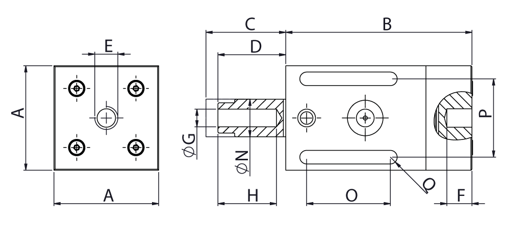
Quaderform F18
| Typ | A | B | C | D | E | F | G | H | I | L | M | N | O | P | Q | R | S | T |
|---|---|---|---|---|---|---|---|---|---|---|---|---|---|---|---|---|---|---|
| F18 | 50 | 89 | 32 | 10 | M10 | 10 | M10 | 26 | 12 | 1/8″ | 1/8″ | 18 | 40 | 37,5 | 6,5 |
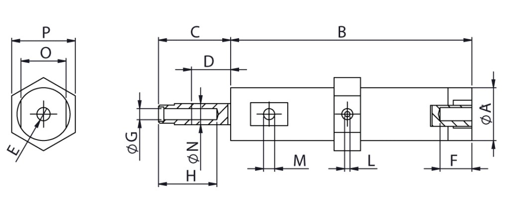
Sechskantform F8
| Typ | A | B | C | D | E | F | G | H | I | L | M | N | O | P | Q | R | S | T |
|---|---|---|---|---|---|---|---|---|---|---|---|---|---|---|---|---|---|---|
| F8 | 20 | 91 | 30 | 5 | M6 | 10 | M5 | 20 | 7 | M5 | M5 | 8 | 17 | 24 |
